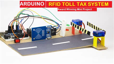
automatic toll collection system using rfid circuit diagram Hey, Friends In This Video I Will Show You How To Make RFID Based Automatic Toll Collection System Using Arduino Nano. Circuit Diagram Or Code -.
Once you have the RFID reader hooked up to the PC, and the driver installed, you should be able to start the ICTransfer.exe utility, then connect it to the RFID reader (Menu\Set (P)\PortSet then Menu\Set (P)\Connect), then .Just dip or tap to pay. Be ready for every sale with Square Reader for contactless and chip. .
0 · rfid toll gate
1 · rfid toll collection system
2 · automatic toll gate system
3 · arduino toll gate
The NFC Android smartphone Nokia 7 plus was released in March 2018 and can scan and use .
rfid toll gate
how to use contactless credit card on uk underground
Automated toll collection system using RFID introduces the Automatic Smart Toll Tax .This project aims to automate toll tax collection for vehicles using Radio Frequency . Circuit Diagram for Toll collection system using RFID. Here is the circuit . Hey Friends In This Video I Will Show You How To Make RFID Based .
Arduino-based Toll Collection System: Combines RFID for automated payments and Infrared .
Hey, Friends In This Video I Will Show You How To Make RFID Based Automatic Toll Collection System Using Arduino Nano. Circuit Diagram Or Code -.In this project, we'll introduce you to the RFID module and Arduino-based Automatic Smart Toll .In this paper, we present the design and implementation of an RFID-based toll collection . The document discusses an electronic toll collection system that uses radio frequency identification (RFID) technology. It describes the key components of RFID tags and readers that allow the system to automatically .
Circuit Diagram & Connection. The circuit for RFID Based Toll Tax Collection System is given below. The circuit is based on the above flowchart with the use of necessary electronic components. The RFID RC522 is an SPI Module. Therefore Connect the RFID SPI Pin to Arduino as follows.
Automated toll collection system using RFID introduces the Automatic Smart Toll Tax Collection System, employing an RFID Module and Arduino. With the increasing congestion at toll plazas, the system aims to streamline the toll tax payment process.This project aims to automate toll tax collection for vehicles using Radio Frequency Identification (RFID) technology. Vehicles are equipped with RFID tags, which are scanned by an RFID reader installed at the toll booth. Circuit Diagram for Toll collection system using RFID. Here is the circuit diagram which makes this project. I have given a step-by-step explanation of how to make connections between different components. We will start with RFID sensor module. Pin with Arduino connections. Sda to D10. Sck to D13.
rfid toll collection system
Hey Friends In This Video I Will Show You How To Make RFID Based Automated Toll Collection System Using ArduinoCode And Circuit Diagram:- https://github.com/.Arduino-based Toll Collection System: Combines RFID for automated payments and Infrared Sensors for vehicle detection to streamline and automate toll operations.Hey, Friends In This Video I Will Show You How To Make RFID Based Automatic Toll Collection System Using Arduino Nano. Circuit Diagram Or Code -.In this project, we'll introduce you to the RFID module and Arduino-based Automatic Smart Toll Tax Collection System. There is a great hurry these days to pay the toll fee at toll.
In this paper, we present the design and implementation of an RFID-based toll collection system using Arduino microcontroller boards. The proposed system leverages Radio-Frequency Identification (RFID) technology for automatic vehicle identification and toll payment, combined with the flexibility programmability of Arduino platforms for system .
The document discusses an electronic toll collection system that uses radio frequency identification (RFID) technology. It describes the key components of RFID tags and readers that allow the system to automatically identify vehicles and deduct toll fares electronically. Circuit Diagram & Connection. The circuit for RFID Based Toll Tax Collection System is given below. The circuit is based on the above flowchart with the use of necessary electronic components. The RFID RC522 is an SPI Module. Therefore Connect the RFID SPI Pin to Arduino as follows.
Automated toll collection system using RFID introduces the Automatic Smart Toll Tax Collection System, employing an RFID Module and Arduino. With the increasing congestion at toll plazas, the system aims to streamline the toll tax payment process.This project aims to automate toll tax collection for vehicles using Radio Frequency Identification (RFID) technology. Vehicles are equipped with RFID tags, which are scanned by an RFID reader installed at the toll booth. Circuit Diagram for Toll collection system using RFID. Here is the circuit diagram which makes this project. I have given a step-by-step explanation of how to make connections between different components. We will start with RFID sensor module. Pin with Arduino connections. Sda to D10. Sck to D13. Hey Friends In This Video I Will Show You How To Make RFID Based Automated Toll Collection System Using ArduinoCode And Circuit Diagram:- https://github.com/.
Arduino-based Toll Collection System: Combines RFID for automated payments and Infrared Sensors for vehicle detection to streamline and automate toll operations.Hey, Friends In This Video I Will Show You How To Make RFID Based Automatic Toll Collection System Using Arduino Nano. Circuit Diagram Or Code -.
In this project, we'll introduce you to the RFID module and Arduino-based Automatic Smart Toll Tax Collection System. There is a great hurry these days to pay the toll fee at toll.In this paper, we present the design and implementation of an RFID-based toll collection system using Arduino microcontroller boards. The proposed system leverages Radio-Frequency Identification (RFID) technology for automatic vehicle identification and toll payment, combined with the flexibility programmability of Arduino platforms for system .


$13.17
automatic toll collection system using rfid circuit diagram|rfid toll gate