rfid based attendance system using pic16f877a It can be directly interfaced with microcontrollers using UART and with PC using an RS232 converter. Just power the module, and it will read any RFID card within range. It will .
$299.99
0 · pic16f877a rfid
1 · pic16f877a interfacing circuit diagram
In honor of Free Game Friday the NFL presents Michael Vick's upset in Lambeau!00:00 - Start9:57 - Michael Vick slings 10-yard TD pass to Shawn Jefferson12:14.
pic16f877a rfid
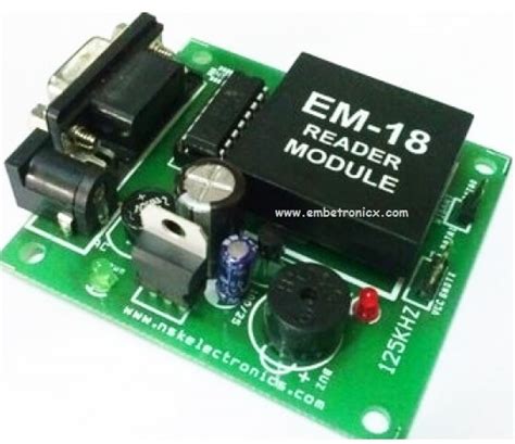
In this project, we chose EM-18 RFID module, which is small-sized, low cost, and power efficient module. EM-18 RFID module use 125 KHz RF frequency to read passive 125 KHz RFID tags. EM-18 module use Oscillator, demodulator and data decoder to read data from a passive card. RFID Tag There are . See more
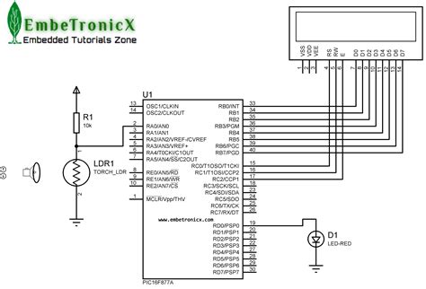
To make this project we need following items- 1. PIC16F877A 2. 20Mhz Crystal 3. 2pcs 33pF ceramic disc capacitor 4. 16x2 Character LCD 5. A breadboard 6. 10k preset pot 7. 4.7k resistor 8. Single strand wires to connect 9. A 5V adapter 10. RF Module EM-18 11. 5V . See moreAs always, first we need to set the configuration bits in the pic microcontroller, define some macros, including libraries and crystal frequency. You can check code for all those in . See moreThe schematic is simple; we connected LCD across port RB and connected the EM-18 module across the UART Rx pin. We have made the . See more
android nfc oyster card
pic16f877a interfacing circuit diagram
This system is designed around PIC microcontroller PIC16F877A and RFID Reader RDM6300, which is 125 kHz reader. It also features LCD 1602 display, a buzzer, servo SG90 and a voltage regulating part.
It can be directly interfaced with microcontrollers using UART and with PC using an RS232 converter. Just power the module, and it will read any RFID card within range. It will . Get this project kit at:- http://www.smartkitprojects.com/rfid-. RFID Based Attendance system each student there will be the different and unique rfid card containing 12 digit. Here we are using PIC Microcontroller PIC16F877A for interfacing RFID. We will simply read the unique identification no. of RFID tags using UART serial communication and display it on 16x2 LCD.This system is designed around PIC microcontroller PIC16F877A and RFID Reader RDM6300, which is 125 kHz reader. It also features LCD 1602 display, a buzzer, servo SG90 and a voltage regulating part.
It can be directly interfaced with microcontrollers using UART and with PC using an RS232 converter. Just power the module, and it will read any RFID card within range. It will output the card’s ID in a serial string, which can easily be read by any microcontroller.
Get this project kit at:- http://www.smartkitprojects.com/rfid-. RFID Based Attendance system each student there will be the different and unique rfid card containing 12 digit. To read the Passive RFID cards and tag, we need a microcontroller with UART hardware. If we select a microcontroller without UART, we need to implement software UART. Here we are using PIC Microcontroller PIC16F877A for interfacing RFID.Question: For this Exercise, use the following components below to design a RFID based attendance system. Use Proteus software to simulate you design and write your code using PIC C Compiler software. Components a. PIC16F877 Microcontroller b.
room. So our main target is to make an attendance marking system to get the attendance without wasting time and to get attendance quickly. We have developed the attendance system using PIC microcontrollers, RFID tags, RFID readers, Arduino Uno board, SD card modules, and Arduino program code to run the program on the Arduino board. The Marking the attendance of the students is very important in universities, colleges, and institutions. The main objective of this work is to make a portable attendance system. We have used RFID technology for this system. The main aim of our system is to get the attendance without wasting time, without any paperwork, and also to get the attendanceMarking the attendance of the students is very important in universities, colleges, and institutions. The main objective of this work is to make a portable attendance system. We have used RFID technology for this system.
android nfc card emulation amiibo
We have used RFID technology for this system. The main aim of our system is to get the attendance without wasting time, without any paperwork, and also to get the attendance details quickly.
Here we are using PIC Microcontroller PIC16F877A for interfacing RFID. We will simply read the unique identification no. of RFID tags using UART serial communication and display it on 16x2 LCD.
This system is designed around PIC microcontroller PIC16F877A and RFID Reader RDM6300, which is 125 kHz reader. It also features LCD 1602 display, a buzzer, servo SG90 and a voltage regulating part.
It can be directly interfaced with microcontrollers using UART and with PC using an RS232 converter. Just power the module, and it will read any RFID card within range. It will output the card’s ID in a serial string, which can easily be read by any microcontroller.Get this project kit at:- http://www.smartkitprojects.com/rfid-. RFID Based Attendance system each student there will be the different and unique rfid card containing 12 digit. To read the Passive RFID cards and tag, we need a microcontroller with UART hardware. If we select a microcontroller without UART, we need to implement software UART. Here we are using PIC Microcontroller PIC16F877A for interfacing RFID.Question: For this Exercise, use the following components below to design a RFID based attendance system. Use Proteus software to simulate you design and write your code using PIC C Compiler software. Components a. PIC16F877 Microcontroller b.
room. So our main target is to make an attendance marking system to get the attendance without wasting time and to get attendance quickly. We have developed the attendance system using PIC microcontrollers, RFID tags, RFID readers, Arduino Uno board, SD card modules, and Arduino program code to run the program on the Arduino board. The Marking the attendance of the students is very important in universities, colleges, and institutions. The main objective of this work is to make a portable attendance system. We have used RFID technology for this system. The main aim of our system is to get the attendance without wasting time, without any paperwork, and also to get the attendance
Marking the attendance of the students is very important in universities, colleges, and institutions. The main objective of this work is to make a portable attendance system. We have used RFID technology for this system.


Make sure you've accounted for a 2mm bleed in your design; this is where your .
rfid based attendance system using pic16f877a|pic16f877a interfacing circuit diagram